72.5KV 3150A 60HZ OUTDOOR HVAC SINGLE PHASE OPERATION vacuum CIRCUIT BREAKR
| ITEM | DESCRIPTION | UNIT | REQUIRED | GUARANTEED | |||
| 1,0 | GENERAL DATA | ||||||
| 1,1 | Manufacturer | Indicate | HEMG | ||||
| 1,2 | Type | Tanque vivo | LIVE TANK | ||||
| 1,3 | Country | Indicate | CHINA | ||||
| 1,4 | Standards of manufacture | IEC 62271-100 | IEC62271-100 | ||||
| IEC 60056 | IEC60056 | ||||||
| 1,5 | Altitude of installation | m.o.s.l | 2500 | 2500 | |||
| 1,6 | Pollution Level | 31mm/kV | 31MM/KV | ||||
| 1,7 | Corrosion index | Medium | IV | ||||
| 2,0 | NOMINAL DATA AND CHARACTERÍSTICS | ||||||
| 2,1 | Frequency | Hz | 60 | 60 | |||
| 2,2 | Characterístics of voltage: | ||||||
| - Nominal Voltage | kV | 60 | 60 | ||||
| - Max voltaje of the system | kV | 72.5 | 72.5 | ||||
| - Max voltaje of the equipment | kV | 72.5 | 72.5 | ||||
| 2,3 | Insulation Level | ||||||
| - Withstand frequency, 1 min. | voltage | at | industrial | kV | 140 | 140 | |
| - Withstand voltage at impulse 1,2/50 ms | kVp | 325 | 325 | ||||
| 2,4 | Characterístics of Current | ||||||
| - Nominal current | A | 1250 | 1250 | ||||
| - Short circuit current | kA | 31.5 | 31.5 | ||||
| - Rated short-circuit current | kAp | 80 | |||||
| - Short circuite duration | s | 3 | 3 | ||||
| 2,5 | - Nominal operating sequence (tripolar reconnection) | O - 0,3s - CO - 3min- CO | O-0.3S-CO-3MIN-CO | ||||
| 2,6 | Operating characteristics: (operating times) | |||
| Duration of maneuver | ||||
| - closing time | ms | <70 | <=70 | |
| -break time | ms | <50 | <= 50 | |
| -Opening time | ms | <35 | <=35 | |
| - Total opening duration for 10% bursting power | ms | Indicate | <= 70 | |
| Symmetrica | ms | Indicate | <=3 | |
| Asymmetrica | ms | Indicate | <=3 | |
| - 30% of rupture power | ms | Indicate | ||
| Symmetrica | ms | Indicate | <=3 | |
| Asymmetrica | ms | Indicate | <=3 | |
| - 60% of ruptura power | ms | Indicate | ||
| Symmetrica | ms | Indicate | <=3 | |
| Asymmetrica | ms | Indicate | <=3 | |
| - 100% of ruptura power | ms | Indicate | ||
| Symmetrica | ms | Indicate | <=3 | |
| Asymmetrica | ms | Indicate | <= 3 | |
| - Close | ms | Indicate | <=70 | |
| Duration of closure between the moment the order is issued and the closing of the contacts | ms | Indicate | 100 | |
| Maximum deviation of simultaneity | ms | Indicate | <=3 | |
| Between the three poles of the switch | Indicate | <=3 | ||
| To the opening | ms | Indicate | <=35 | |
| To the close | ms | Indicate | <=70 | |
| 2,7 | First pole opening factor | 1,5 | 1.5 | |
| 2,8 | Maximum opening time difference between two diferent poles | ms | 3 | 3 |
| 2,9 | Transient Recovery Voltage (TRV) | kV | Indicate | 181.8 | ||||
| 2.1 | Rate of rise recovery voltage (TRV) | KV/ms | Indicate | 0.72 | ||||
| 2,11 | Breaking Chambers: | Power | and | Interruption | ||||
| - Arc extinción way | SF6 | SF6 | ||||||
| - Number of cut-off chambers per phase | u | 1 | 1 | |||||
| - Number of capacitors of distribution | Indicate | 0 | ||||||
| - Opening distance between contacts | mm | Indicate | 27MM | |||||
| - Pressure of the extinguishing medium in the extinguishing chambers | MPa | Indicate | 0.55 | |||||
| 2,12 | Control device | |||||||
| - Model | Indicate | CT-1 | ||||||
| - Functioning | One -Three phase | SINGLE PHASE OPERATION ,THREE PHASE | ||||||
| - Type of mechanism of operation | By spring / engine | BY SPRING ENGINE | - | |||||
| - Load of mechanism | 600W | |||||||
| . Manual | Yes | YES | ||||||
| . Eléctric | Yes | YES | ||||||
| - Motor supply voltage | Vdc | 110 +10%/- 20% | 110(-20% +10%) | |||||
| - Auxiliary voltage (controls) | Vdc | 110 +10%/- 20% | 110V(-20%+10%) | |||||
| - Current of the engine | A | Indicate | 8A | |||||
| - Power of the engine | W | Indicate | 600W | |||||
| - Contacts auxiliars | 10 NO + 10 Nc | 10NO+10NC | ||||||
| Maximum allowed number of starts per 24 hours, time of each operation | Indicate | 1000 | ||||||
| Oil type of control device | Indicate | GREESE | ||||||
| Amount of oil per switch | Indicate | 15G | ||||
| Operation in case of loss of energy | ||||||
| With closed switch | Indicate | 350W | ||||
| With closed open | Indicate | 250W | ||||
| 2,13 | BUSHING | |||||
| - Brand | Indicate | PUKO | ||||
| - Type | Indicate | ZSW | ||||
| - Material | Porcelain | PROCELAIN | ||||
| - Total leakage distance | mm | Indicate | 4100 | |||
| - Specific leakage distance | mm/kV | 31 | 31 | |||
| - Electrodynamic flexural load | N | Indicate | 6000 | |||
| - Capacitance | PF | Indicate | 0.48 | |||
| - Factor of dissipation | % | Indicate | <=0.5 | |||
| 2,14 | CHARACTERÍSTICS DIELÉCTRICS | |||||
| - Extinguishing fluid pressure in interruption chambers (gas) | the | Bar | Indicate | 0.55MPA | ||
| - Guaranteed number of IN interruptions without changing the extinguishing medium | Indicate | 20TIMES | ||||
| - Of 0,5 Icc without changing extinguishing fluid | the | Indicate | 1000TIMES | |||
| Maximum annual SF6 gas loss | 0.5% | <=0.5% | ||||
| 3,0 | CIRCUITS AUXILIARS | |||||
| 3,1 | Coils of close and open : | |||||
| - Number of trigger coils | 2 | 2 | ||||
| - Number of coils of close | 1 | 1 | ||||
| - Voltage nominal | Vcc | 110 15% | +10%/- | 110(-15% TO +10%) | ||
| - Power of the coils | W | Indicate | 300w | |||
| 3,2 | Heating of the control box and drive: | |||||
| - Voltage nominal | Vca | Indicate | 220v | ||
| - Power | W | Indicate | 100 | ||
| - Thermostat Control Range | ºC | Indicate | <=15 | ||
| - Frequency | Hz | 60 | 50 | ||
| 3,3 | Internal blocks in the control device: | ||||
| - Closing Interlock Voltage | Vdc | 110 20% | +10%/- | 110 +10%/-20% | |
| - Opening Interlock Voltage | Vdc | 110 20% | +10%/- | 110 +10%/-20% | |
| - Voltage of anti-pumping relays | Vdc | 110 20% | +10%/- | 110 +10%/-20% | |
| 3,4 | Alarms: | ||||
| - Low pressure of gas | Yes | yes | |||
| - Failure of control device | Yes | yes | |||
| 3,5 | Signaling | ||||
| - Counter of operations of the switch | Yes | yes | |||
| - Mechanical position indicator | Yes | yes | |||
| 4,0 | AUTOMÀTYC CLOSE | ||||
| Alarms | Yes | yes | |||
| - Closing deadlock | Yes | yes | |||
| - Opening Interlock | Yes | yes | |||
| Discordance | Yes | yes | |||
| Position signaling | Yes | yes | |||
| Counter of maneuvres of the circuit breaker | Yes | yes | |||
| Mechanical position indicator | Yes | yes | |||
| Position auxiliary contacts mechanically connected to the control device (minimum 7) | Indicate | 10NC+15NO | |||
| 5,0 | EXTREME OPERATING TEMPERATURES | oC | Indicate | -30ºC,+85ºC |
| 6,0 | HEATINGS | |||
| - Heating of the contacts in continuous operation under IN switch | oC | Indicate | <=15 | |
| - Heating of the contacts under Icc during the maximum permissible time | oC | Indicate | <=15 | |
| - Heating in continuous operation of the extinguishing medium under In | oC | Indicate | <=15 | |
| 7,0 | SUPPLY SUPPORT AND ANCHORING BOLTS | Yes | yes | |
| 7,1 | The metal frames needed for the Switch, will include the supply, They could be fabricated for a direct fixing, also, the structures support. | Yes | yes | |
| 7,1 | Galvanized support and hardware | um | 100 | 100uM |
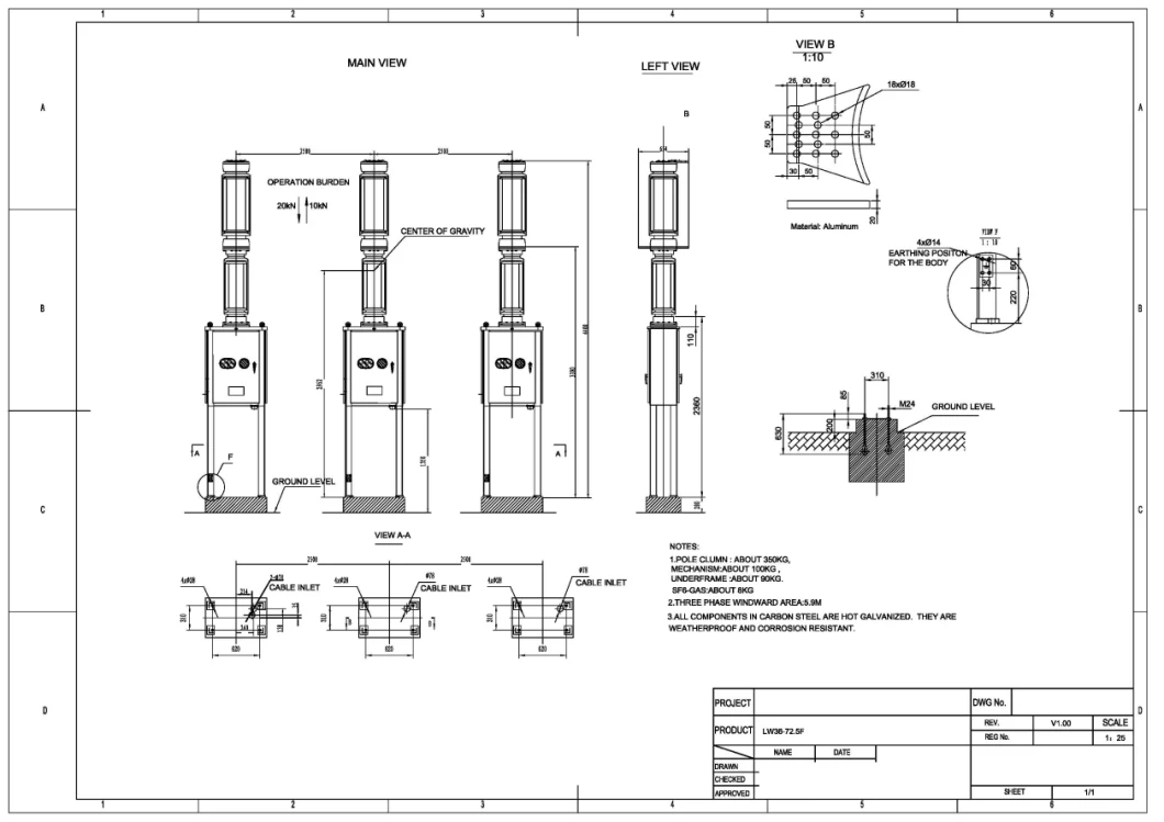
| 8,0 | MASSES, DIMENSIONS, EFFORTS, SCHEMES AND NOTES | |||
| 8,1 | Weights: | |||
| - Total weight of the circuit breaker | kg | Indicate | 1800 | |
| - Total weight of the control box | kg | Indicate | 90 | |
| - Weight of the chamber | kg | Indicate | 300 | |
| - Weight of 1 pole for transport | kg | Indicate | 1000 | |
| 8,2 | Dimensions: | |||
| - Dimensions of terminal HV | mm | Indicate | 2041 | |
| - Dimensions of the box for transport | mm | Indicate | SEE TRANSPORT LIST | |
| - Drawing of the outer dimensions of switch completely assembled and with all its accessories | Nº | Indicate | SEE LAYOUT DRAWING | |
| - Drawing of the external dimensions of the pole of the switch to the assembly (placement on site with indications of normal means of lifting and transport) | Nº | Indicate | SEE LAT DRAWING | |
| - Drawing of exterior dimensions of the largest piece, for transport purposes | Nº | Indicate | SEE TRANSORT LIST |
| 8,3 | Efforts : | ||||||
| - Permissible longitudinal effort on the terminal of H.V. | N | Indicate | 1250 | ||||
| - Permissible transverse force on terminal of H.V. | N | Indicate | 750 | ||||
| - Effort transmitted to foundation foundations during operation | Indicate | 1000 | |||||
| At close | kN | Indicate | 35 | ||||
| At open | kN | Indicate | 26 | ||||
| 8,4 | Schemes: | ||||||
| - Drawing of the external dimensions of the Switch Assembled with all its accessories | Yes | YES | |||||
| - Drawing the outer dimensions of the largest piece for transport purposes | Yes | YES | |||||
| - Drawing of the support structure | Yes | YES | |||||
| - Drawing with the dimensions of packing box | Yes | YES | |||||
| 8,5 | Notes: | ||||||
| - Note descriptive of breaker | Yes | YES | |||||
| - Note descriptive of control device | Yes | YES | |||||
| - List of equipments | reference | supply | similar | Yes | YES | ||
| 9,0 | MINIMUM DISTANCES | ||||||
| - Distance between pole axes | mm | 1750 | 1750 | ||||
| - Minimum height of the base of the support to the bottom of the porcelain of the insulator | mm | Indicate | 2500 | ||||
| 10,0 | SEISMIC CONDITIONS | Horizontal seismic acceleration of 0.5g and vertical seismic acceleration | 0.5G/0.2G | ||||
| of 0.2g | YES | |||
| 11,0 | TESTS | IEC 62271- 100 | YES |